TM55-2840-251-23
4-1 POWER SECTION (AVIM) (Continued)
4-1-2 INSTALLATION (Cont)
10. Continue lowering power
section (38) until flange C faces
are mated. Install dee-head
bolts (35) from gas generator
case side and fit push-pull cable
clamp bracket (37) and self-
locking nuts (36). Torque nuts
(36) to 36 to 40 inch-pounds.
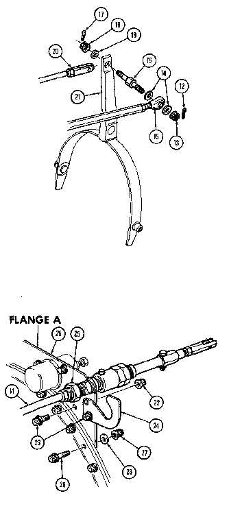
11. If lifting bracket (26) was
removed from flange A, refit
bracket (26) with seven bolts
(29), nuts (27) and washers (28).
Torque nuts (27) to 36 to 40 inch-
pounds.
12. If retaining plate (24) is
to be fitted to lifting bracket
(26), ease push-pull cable (11)
into lifting bracket, then secure
retaining plate (24) with two
bolts (23) and nuts (22). Torque
nuts (22) to 36 to 40 inch-
pounds.
13. Tighten nut (25), torque
to 80 to 100 inch-pounds and
lockwire (E.5).
14. Insert spacer (19) in hole
at top of reversing lever (21),
fit clevis (20) over lever (21)
and pass shouldered stud (16)
through. Secure with spacer (19)
and nut (18). Torque nut (18) to
12 to 18 inch-pounds and fit
cotterpin (17).
15. Assemble rod end connector
(15), with one washer (14) each
side, to shouldered stud (16).
Fit nut (18), torque to 12 to 18
inch-pounds and lock with
cotterpin (17).
GO TO NEXT PAGE
4-8