TM55-2840-251-23
6-5
FUEL MANIFOLD ASSEMBLY (Contin ued)
6-5-2 INSTALLATION (Cont)
5.
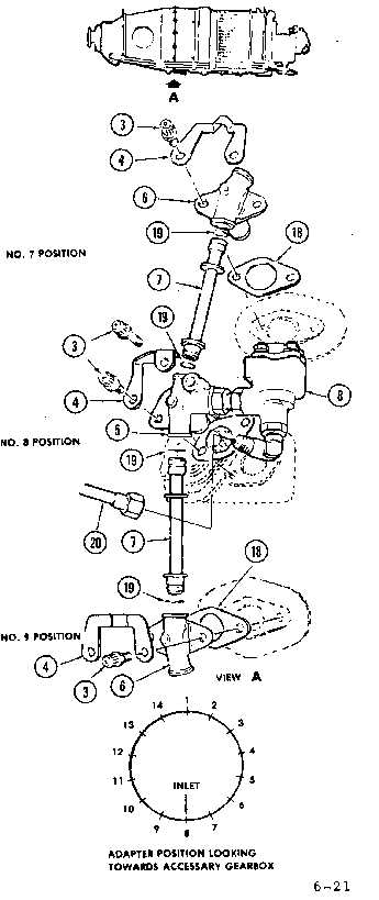
Install assembly of fuel inlet adapter (5) and dump
valve (8), with new gasket (18), on gas generator case
boss at 6 o'clock position. Loosely secure with two bolts
(3).
6. Lubricate 28 new preformed packings (19) with
Petrolatum (E.20) and install one on each end of the 14
fuel transfer tubes (7).
7.
Install transfer tube (7) in each inlet adapter (5)
orifice, as shown. Install previously index-marked
adapters (Task 6-5-1), complete with new gaskets, at
No. 7 and 9 positions, over the free end of installed
transfer tubes. Align adapters with relevant gas
generator case bosses and continue installing transfer
tubes (7) and manifold adapters (6), complete with new
gaskets, in the sequence 6,5,4,3,2,10,11,12,13,14.
GO TO NEXT PAGE
6-21

