TM55-2840-251-23
6-11 FUEL LINES AND FITTINGS (Continued)
6-11-4 INSTALLATION
1.
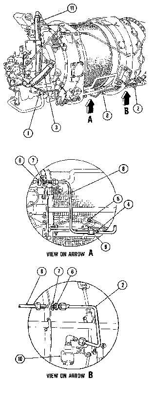
Install rigid tube (8) through center and rear fireseals
and temporarily secure with washers (7) and nuts (6).
2.
Install loop clamp (9) on tube assembly (8) and
secure to bracket on air inlet screen flange with bolt (5)
and self-locking nut (4). Torque nut to 36 to 40 inch-
pounds.
3.
Torque nuts (6) to 65 to 75 inch-pounds. Do not
lockwire at this stage.
4.
Install rigid tube (2) on fuel dump valve (10) elbow
and on tube (8) at center fireseal. Check torque locknut
on dump valve elbow to 38 to 42 inch-pounds, torque
tube (2) connections to 30 to 100 inch-pounds and
lockwire (E.5) to locknut on elbow and to nut (6).
5.
Install rigid tube on fuel control unit and on tube (8)
at rear fireseal. Torque connections to 90 to 100 inch-
pounds and lockwire (E.5) to nut (6) and fuel control
elbow.
6.
Install flexible tube (3) on fuel pump adapter and on
fuel control unit elbow. Torque connections to 270 to
300 inch-pounds and lockwire (E.5).
7.
Install flexible tube (11) on fuel pump and oil-to-fuel
heater elbow. Torque connections to 450 to 500 inch-
pounds and lockwire (E.5).
8. Inspect.
FOLLOW ON MAINTENANCE:
None
END OF TASK
6-52


