TM 55 4920-328-13
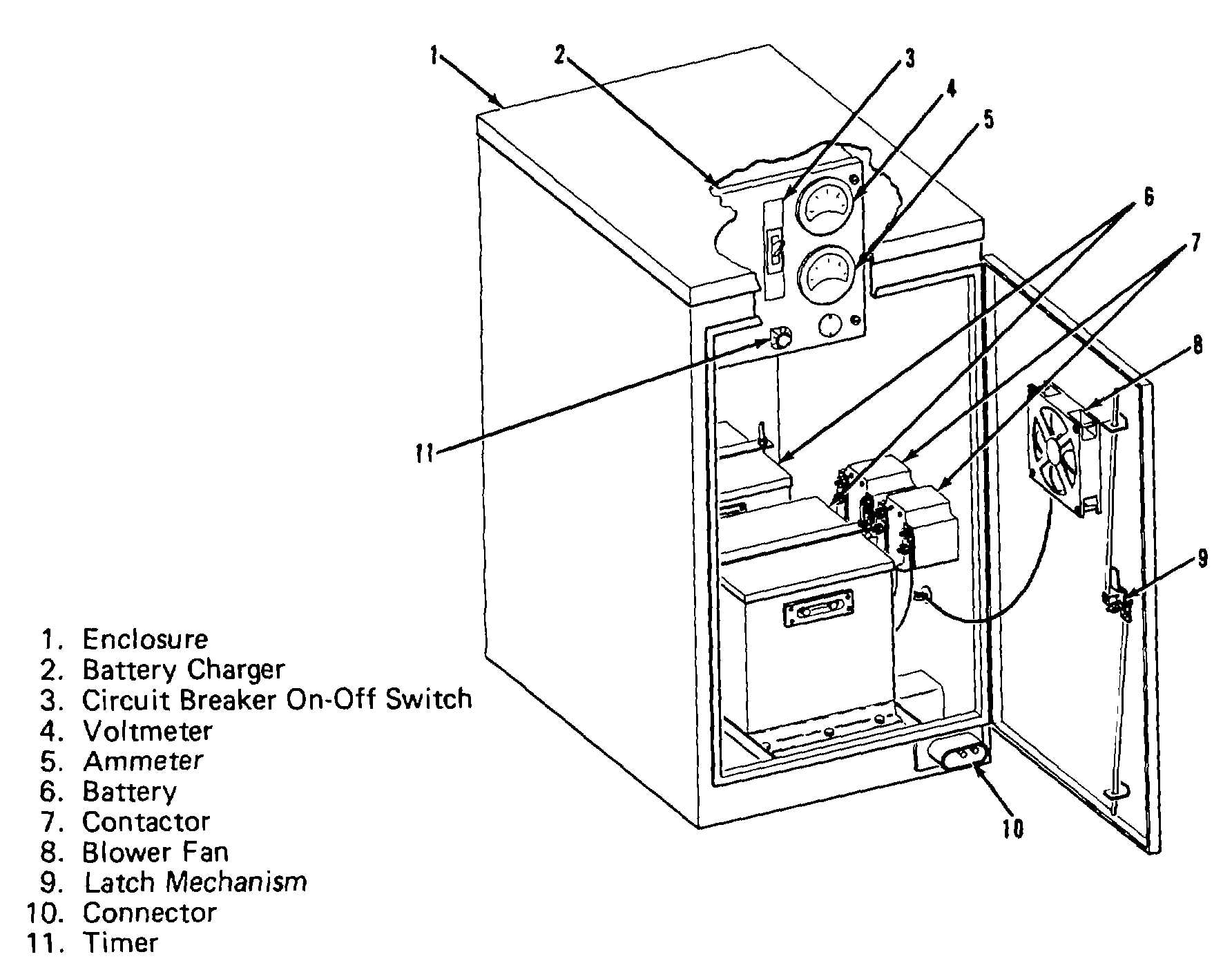
Figure 1-6 Electric Start System.
(4) Electric start system.
NOTE
U.S. Army (USATSARCOM) authorized
ECP No. MEG-01, dated March 26,
1981, identifies the replacing of the
gasoline
engine
driven
hydraulic
starting unit and the battery starting
system with a Christie Rectifier Power
Supply
starting
system.
(Army
supported electrically driven units are
currently available.)
(a) The electric start system (figure 1-6) is
mounted on the left center deck of the test trailer
assembly. The system provides 24v dc electrical power
to energize each gas turbine engine starter, when so
equipped (some engines are provided with hydraulic
starting units). The electric start system is contained in
a sheet metal waterproof enclosure ( 1 ) approximately
27 inches long, 20
inches wide, and 36 inches high. The system (shown
schematically in figure 1-7), consists of two heavy-duty,
MS-type, 28-volt, nickel-cadmium batteries (6, figure 1-
6), one of which is on line while the other is provided as
a spare, and two heavy-duty line contactors (7). Wiring
from the terminals of the batteries consists of No. 4
AWG welding cable, required by the heavy current drain
during engine starting. The unit is also provided with a
battery charger (2) to maintain the battery charge. The
charger is powered by 220v ac, 60 Hz, single-phase
power provided by the generator set through TRICKLE
CHARGER circuit breaker CB13 I9, figure 2-9). The
interior of the enclosure is cooled by a fan (8, figure 1-6)
which exhausts fumes and warm air to atmosphere
through a duct on the forward side of the unit. Servicing
information for the batteries is contained in chapter 2 of
this technical manual.
(b) Closure of the START switch S23 (31,
figure 1-24) provides 28v dc power to energize
Change 4 1-9


