TM 1-1500-204-23-1
·
When hot starts or tall pipe temperatures
exceed maximum allowable limit for given
operating condition, inspection or replacement
shall be accomplished in accordance with the
applicable maintenance manual.
·
When oil system is contaminated with metal
particles,
proceed
as
directed
in
the
maintenance manual.
b.
Component Replacement. Criteria Replace
individual turbine engine components as specified In the
applicable maintenance manual.
8-8. Marking of Defects on Turbine Engines.
Defects In removed parts may be marked by use of a
felt-tip marker.
8-9. Turbine Engine Mounts. A typical engine
mounting
system
consists
of
bipod
and
tripod
assemblies braced by tube assemblies. For specific
details of the system, refer to engine section of the
applicable maintenance manual. Repair bent, distorted,
or chafed areas of mount as specified in the applicable
maintenance manual. After repair of any component of
engine mount, accomplish a thorough visual and
magnetic particle inspection.
8-10. Preservation and Depreservation of Turbine
Engines. The preservation and depreservation
procedures for each type of turbine engine is specified
In the applicable aircraft maintenance manual
8-11. Removal and Installation of Turbine Engines.
Removal and installation of turbine engines is explained
In the following paragraphs. Refer to the applicable
maintenance manual.
a.
Preparation for Removal. Accomplish the
following general steps before removal.
(1) Adequately secure the aircraft either with
wheel chocks or with tiedown provisions; attach ground
wire or cable to aircraft.
(2) Open the nacelle doors and support them
with the struts. Verify that no external power is
connected to the aircraft and that the electric power
switch is off.
(3) Remove the mount access plates from both
sides of the nacelle structure.
(4) Remove the engine air-conditioning duct
access plate, and disconnect the duct from the engine.
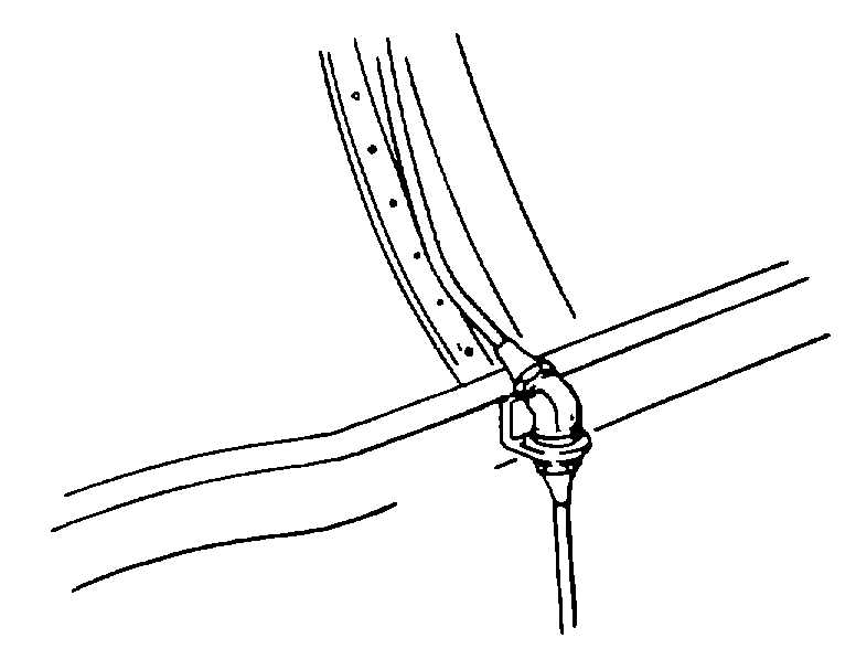
(5) Disconnect the turbine discharge pressure
pickup line as shown in figure 8-19.
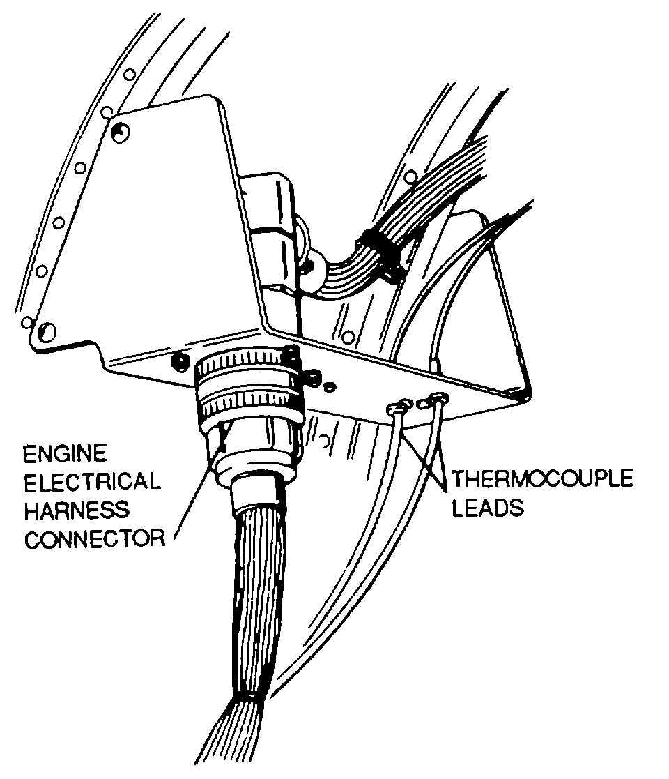
(6) Disconnect the electrical wiring and the
thermocouple leads from the connectors as shown in
figure 8-20.
(7) Disconnect the fuel line by removing the
bolts from the hose flange as shown in figure 8-21.
Figure 8-19. Turbine Discharge Pressure Pickup
Line
Figure 8-20. Electrical Disconnect
8-20


