TM 1-1500-204-23-1
9-4. Troubleshooting of Landing Gear Systems.
The troubleshooting procedures for electrical and
hydraulic landing gear systems is in the applicable
maintenance manuals.
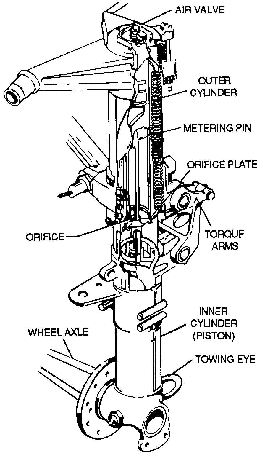
9-5. Shock Struts. Shock struts, as shown in figures 9-
4 and 9-5, are self-contained hydraulic units that support
an aircraft on the ground and protect the aircraft
structure by absorbing and dissipating the tremendous
shock loads of landing. Shock struts must be inspected
and serviced regularly to function efficiently.
a.
Shock Strut Operation. The compression stroke
of the shock strut begins as the aircraft wheels touch the
ground, the center of mass of the aircraft continues to
move downward, compressing the strut and sliding the
inner cylinder into the outer cylinder. The metering pin
is forced through the orifice and, by its variable shape,
controls the rate of fluid flow at all points of the
compression stroke. In this manner the greatest
possible amount of heat is dissipated through the walls
of the shock strut. At the end of the downward stroke,
the compressed air Is further compressed, limiting the
compression stroke of the strut. The extension stroke
occurs at the end of the compression stroke as the
energy stored in the compressed air causes the aircraft
to start moving upward in relation to the ground and
wheels. At this instant, the compressed air acts as a
spring to return the strut to normal. It is at this point that
a snubbing or damping effect is produced by forcing the
fluid to return through the restrictions of the snubbing
device (See figure 9-6 ).
b.
Shock
Strut
Servicing.
The
following
procedures are typical of those used in deflating a shock
strut, servicing with hydraulic fluid, and reinflating
(1) Position the aircraft so the shock struts are
in the normal ground operating position. Make certain
that personnel, workstands, and other obstacles are
clear of the aircraft. (Some aircraft must be placed on
lacks to service the shock struts).
(2) Remove the cap from the air valve.
(3) Check the swivel hex nut for tightness with
a wrench
WARNING
Always stand to one side of the
valve, since high-pressure air can
cause serious injury, e.g., loss of
eyesight .
Figure 9-3. Landing Gear Safety Circuit
Figure 9-4. Landing Gear Shock Strut of the
Metering Pin Type
9-4