TM 1-1500-204-23-1
NOTE
Type AN943 internally threaded rod
ends are equipped with a witness
hole a short distance from the
threaded end to ensure adequate
thread engagement when installed
on an externally threaded rod end.
Proper
thread
engagement
is
ensured
when
threads
of
an
externally threaded rod end can be
seen and a piece of safety wire
cannot be passed through the hole.
If you can pass a piece of 0.020
safety wire through the hole, the rod
is not screwed in far enough
3 Install tube assembly with
correct bolts, nuts, and washers
NOTE
When connecting a ball beanng rod
end, install a plain or countersunk
washer, MS20002, of appropriate size
under the attaching nut and bolt head
to prevent any possibility of rod end
slipping off over the bearing retaining
nut or bolt head. Attaching nut and
bolt must clamp tightly the inner race
of bearing to face of washer and
supporting structure. Use caution
when installing washers so that full
movement of rod end is not limited.
Nuts and bolts that are only fingertight
do not use the beanng for the purpose
for which it was intended. Control
tubes using clevis rod ends may have
washers, if required, installed under
bolt and nut heads on outside of fork
or between fork and bearing, if space
permits. Tighten nuts to torque values
shown in applicable aircraft manual.
4
Check
for
freedom
of
movement, full travel, and excessive side play.
5 Secure rod ends, bolts, and
nuts with applicable safety devices.
(6)
Rod ends. Rod ends are used on
push-pull linkage as attachment points and to effect
minor adjustments. Rod ends are available with
threaded, clevis, and bearing ends. Those with
internally threaded shanks are used on threaded control
rods or control tube assemblies which have threaded rod
ends Other rod ends are used to make up control tube
assemblies Rod ends are used to make adjustments in
control tube length and usually are safetied with a
checknut or lockwire
(a) Inspection of rod ends. Clean and
inspect rod ends using the following procedures:
1 Check for cracks and breaks.
2 Check for threaded portion for
damaged threads
3
Check
for
evidence
of
corrosion.
4 Check for bent or misaligned
clevis forks and elongated bolt holes
5 Thoroughly clean, inspect,
and lubricate bearings in accordance with TM 55-1500-
322-25.
(b)
Repair of rod ends. Minor repairs
maybe accomplished using the following procedures:
1 Smooth out small nicks and
scratches with fine abrasive cloth, Federal Specification
P-C-451.
2
Correct
minor
thread
irregularities by chasing threads with a tap or die.
3 Replace defective bearings.
4 Major defects will require
replacement of rod end.
(c)
Installation of rod ends. Install
rod ends and control tube assembly as a unit. Refer to
paragraph 9-12f (5)(c).
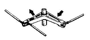
(7)
Bellcranks. Bellcranks, as shown in
figure 9-30, change direction of motion and transmit
motion to parts such as control rods, cables, and torque
tubes Replace all worn, bent, or otherwise defective
bellcranks.
Figure 9-30. Bellcrank
9-28