TM 1-1500-204-23-1
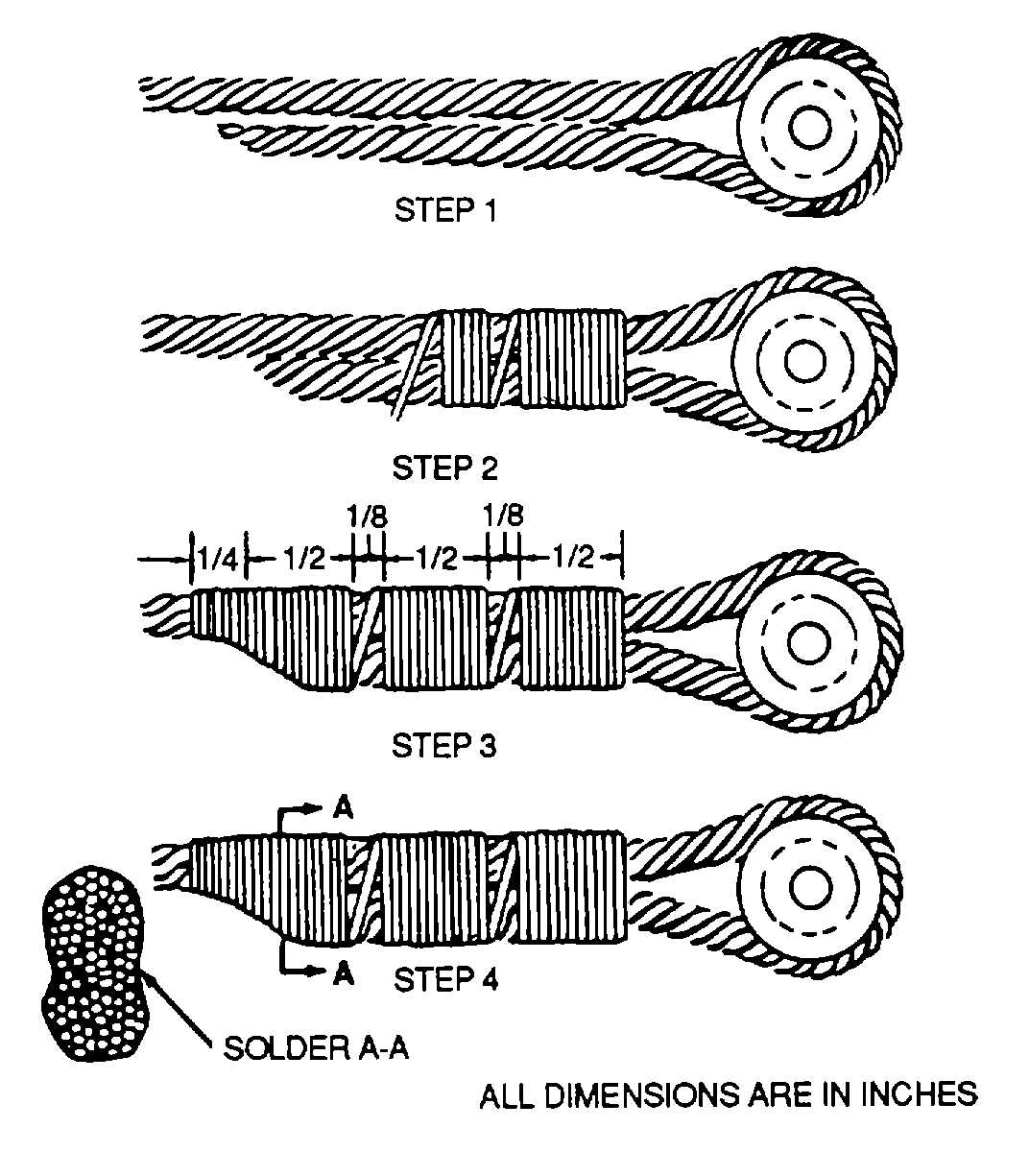
Figure 9-24. Wrapped Solder Splice
4
Allow
wrapping
to
extend
approximately 1/4 inch beyond free end.
5 Dip wrapping in tin-lead solder,
Federal Specification QQ-S-571.
NOTE
Carefully sweat solder into cable and
about wrapping
6 Apply solder until wrapping wire is
barely discernible, and ensure that open spaces
between wrap sections are thoroughly impregnated with
solder.
7 After splice has cooled, thoroughly
wipe clean and remove all solder residue.
8 Wipe cable and impregnate
spliced section with corrosion preventive compound,
MIL-C-16173, Grade I.
9 Carefully inspect splice. A
wrapped soldered splice, easily bent with fingers, is
unsatisfactory because of lack of solder penetration.
NOTE
Cracks in solder located between
wrapping wire and short space
provide between wraps is a positive
indication
of
slippage
in
wrap
soldered splice.
(5) Testing of cables and splices.
Test all cables and splices prior to installation using the
following procedures:
WARNING
A suitable guard should be placed
over cable, during testing, to prevent
injury in event of cable failure.
(1)
Arrange
cable
to
simulate
installation,
including pulleys, when required.
(2) Apply test load (refer to Table 9-3) gradually to
one end of the cable for 3 minutes.
Table 9-3. Cable Test
Cable size
(inches)
Load in pounds1
1/16
288
3/32
552
1/8
1200
5/32
1680
3/16
2520
7/32
3360
1/4
4200
9/32
4800
5/16
5870
3/8
8640
160 percent of minimum allowable breaking strength.
9-23


