TM 1-1500-204-23-1
(a)
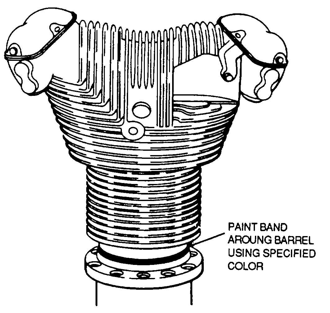
Identification. Cylinders will be color
coded around the barrel between the attaching flange and
the lower barrel cooling fin with a 1/2-inch wide band of
enamel, heat-stable, cadmium sulphide paint (see figure
7-12). The cylinder sizes and colors are listed below
Standard Cylinder - Aluminum or Black
Chrome Plated - International Orange
0.010 Inch Oversize - Green
0.015 Inch Oversize - Gray
0.020 Inch Oversize - Yellow
NOTE
Chrome-plated cylinders are further
Identified
as
illustrated
In
the
following example 6-44, SAX-3, 20
would designate the third cylinder
plated by San Antonio Air Material
Area in June 1944, and the cylinder
was 0.020 inch oversize when plated.
(b)
Liquid lock. When an engine is shut
down, the warm residual oil clinging to the power section
surfaces flows downward toward lower cylinders. Some
of this oil seeps past piston rings, accumulating in the
combustion chamber. When sufficient liquid is present,
the true compression ratio will be raised and extremely
high pressure will be produced when the piston moves
down on the compression stroke. These pressures can
damage the cylinder, piston, or rod. The piston may
actually press the liquid, forming what is known as a
hydraulic or liquid lock (see figure 7-13). Observe the
following precautions:
CAUTION
Do not rotate propeller in reverse
direction of normal engine rotation.
This will push the liquid Into intake
pipes and return to cylinders on the
next intake stroke.
When propeller is rotating in the normal
direction, the operator must be alert for any sign
of
piston
being
forced
against
high
compression,
evidenced
by
a
sudden
resistance, slowdown, or stoppage which would
indicate an excess amount of liquid in the lower
cylinder
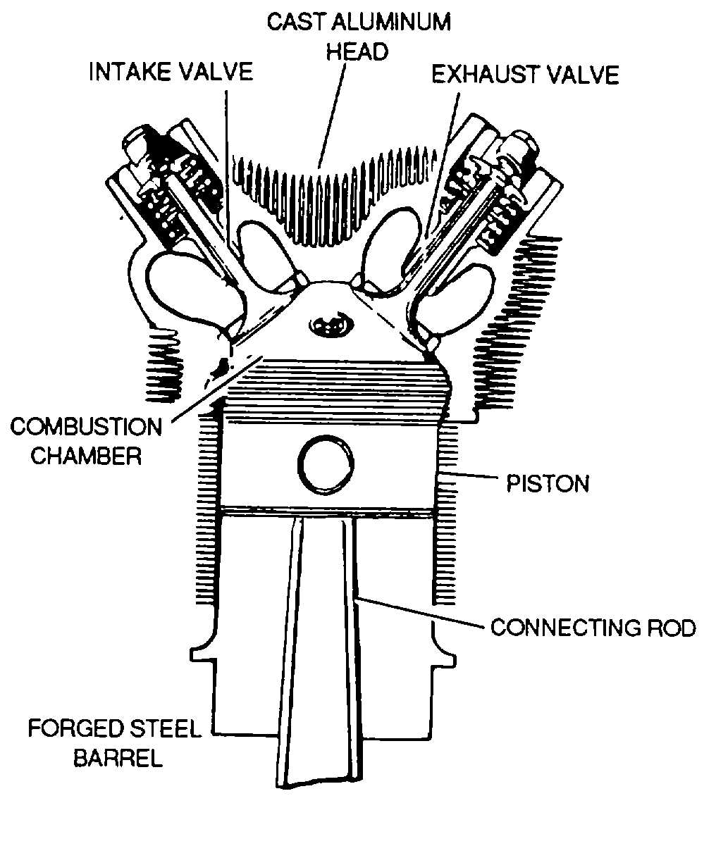
Figure 7-11. Cylinder Assembly
Figure 7-12. Marking of Cylinder
7-9