TM 1-1500-204-23-2
(7)
While socket is still in vise, mark hose position with paint, grease pencil, or tape. Refer to step 3,
figure 4-50A.
(8)
Lubricate Inside of hose, nipple thread, and all mating surfaces. Refer to step 4, figure 4-50A. Use
SAE 30 lubricating oil.
(9)
Carefully insert and engage nipple and socket threads while holding hose In position with other hand.
Refer to step 5, figure 4-50A Make sure that hose does not push out of socket by observing mark make in step 3, figure
4-50A. On flange elbow fittings, drop flange over threaded end of nipple. Nipple shoulder must fit into counterbore of
flange.
(10)
While still holding hose, complete assembly of nipple and socket by use of a wrench. Refer to step 7,
figure 4-50A. The method of determining proper tightening shall be measurement of gap between socket and nipple with
a feeler gage The gap shall be 0.000 Inch minimum to 0.031 inch maximum. After completing assembly of nipple into
socket, check hose position mark that was made in step 3, figure 4-50A. No push out Is permitted for size -3 through -10
In sizes -12 through -32, 1/32 inch is allowable.
(11)
On hose assemblies having angle fitting on both ends, adjustment may be necessary to obtain the
desired position angle between to elbows Refer to step 8, figure 4-50A In order to prevent backing elbows to position, the
following procedure should supplement steps 6 and 7.
(a)
Tighten both elbows to 0.040 if an Inch clearance of socket then start to position for relative
angle between elbows. Refer to step 7, figure 4-50A.
(b)
Finish assembly by adjusting both elbows Backing off to position should be avoided Maximum
allowable gap between hex and socket is 0. 031 of an inch.
(c)
The tolerance on angular alignment is f5 degrees on hose lengths up to 36 inches and i 10
degrees on hose lengths greater than 36 inches.
NOTE
Check for hose push-out by observing hose position mark No change should be evident.
(12)
Clean, inspect and proof test as instructed In paragraph 4-5f and table 4-17. Identify as instructed in
paragraph 4-5g.
(13)
After installation on aircraft, in addition to all regular Inspections, check that position and shape
conform to general conditions shown in aircraft parts manual.
4-6.
Installation of Flexible Nose. General Instructions to be followed when Installing flexible hose are outlined in
paragraphs a through k and in figure 4-57.
a.
Lubrication. Never, under any conditions, use oil on self-sealing hose as an aid to installation Oil or water
may be used on all other types of fuel, oil, and
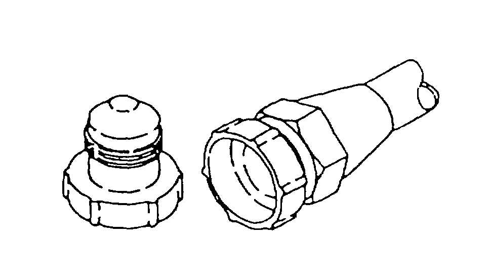
Figure 4-51. Plastic Protective Dust Plug and Moisture Seal (AN-SAE Threaded)
Change 2 4-75