TM 1-1500-204-23-2
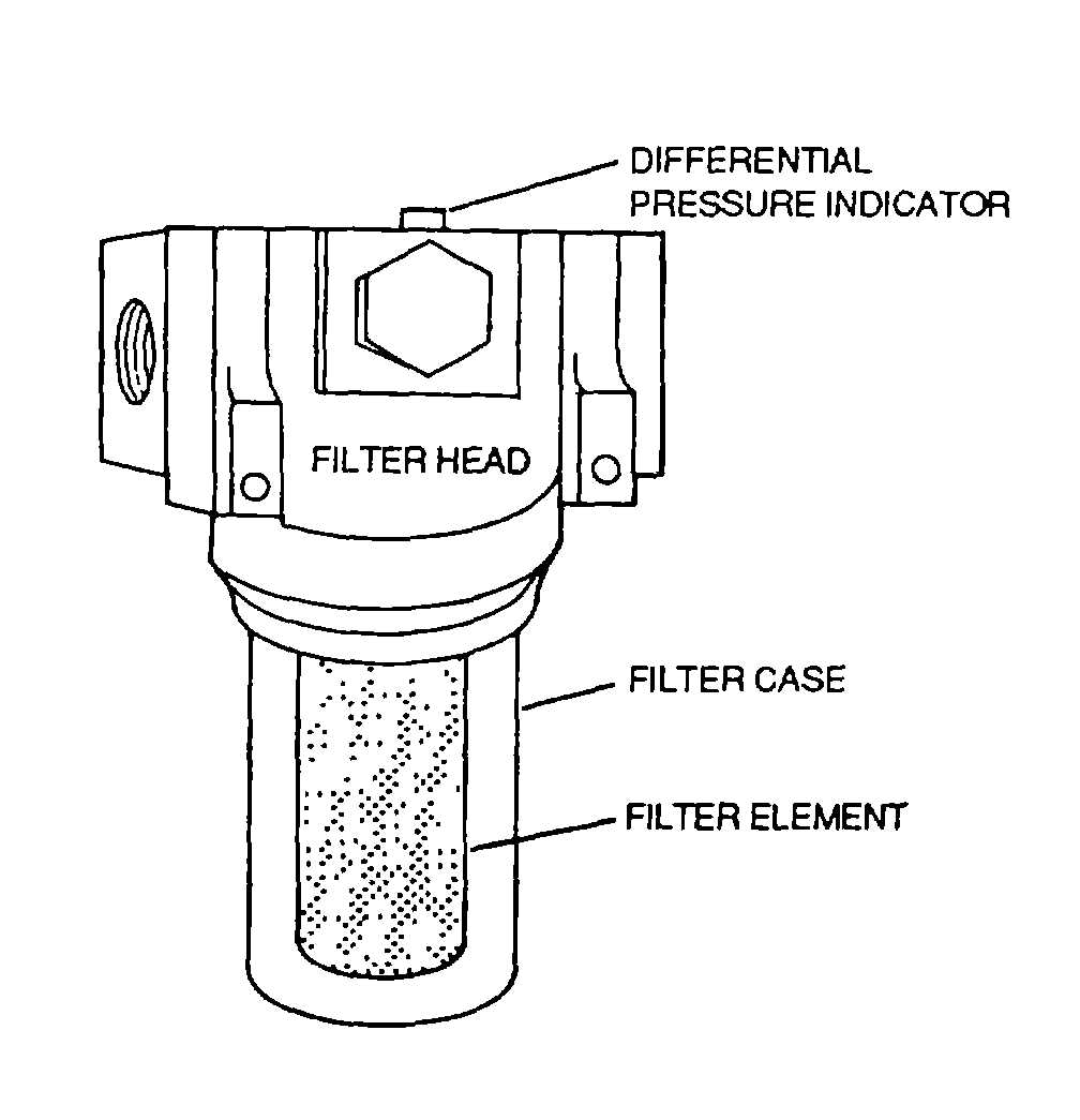
outlet port if the filter element becomes clogged with foreign matter. The filter case is the housing that holds the element
to the head assembly and is the part that is removed during replacement of the filter element.
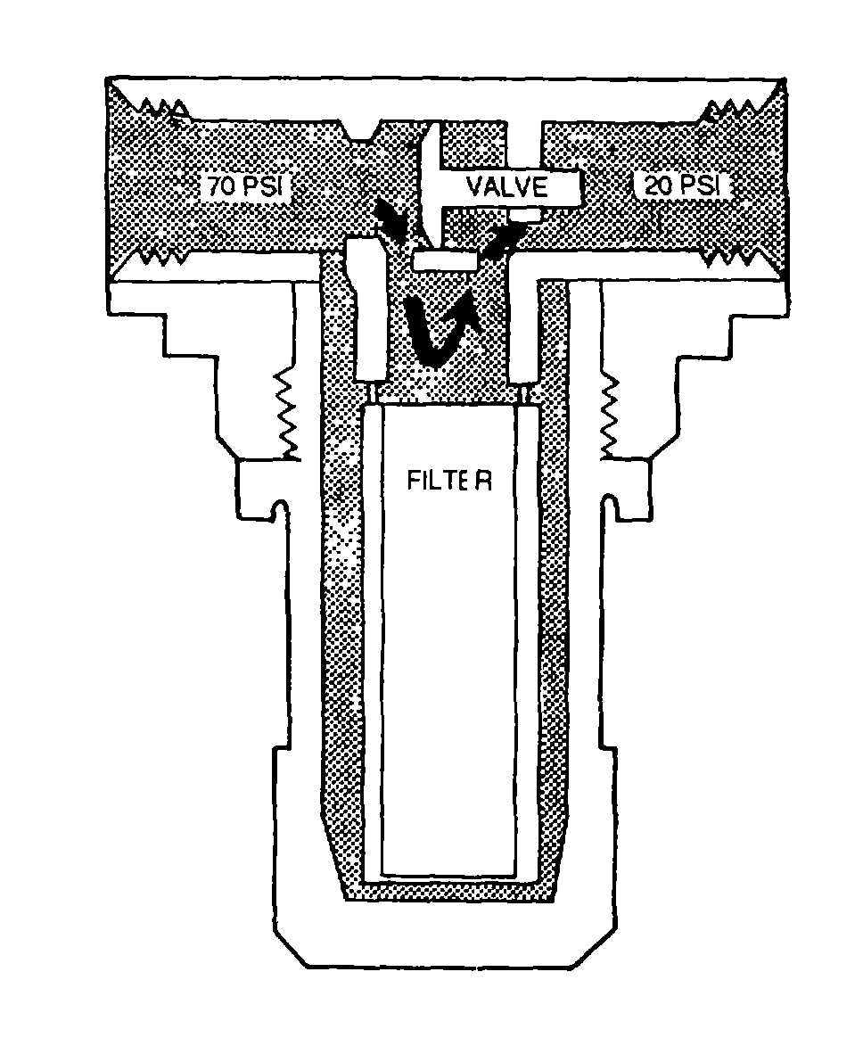
(1) Normal flow. Figure 4-97 shows a filter in normal flow. Hydraulic fluid enters the filter through the inlet port
In the body and flows around the element inside the filter bowl. Filtering takes place as the fluid passes through the
filtering element at the hollow core, leaving the dirt and impurities on the outside of the filter element Filtered fluid then
flows from the hollow core to the outlet port in the body and into the system
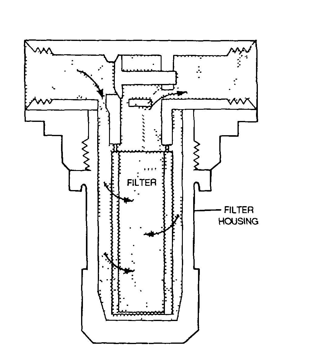
(2) Clogged filter. Figure 4-98 shows a filter that is clogged. The bypass pressure relief valve In the body allows
the fluid to bypass the filter element and pass directly through the outlet port. In most filters on this type, the relief valve
Is set to open If the pressure drop exceeds 50 psi, for example, if the pressure at the filter inlet port was 70 psi and the
pressure at the outlet port dropped below 20 psi, the relief valve would open.
(3) Differential pressure indicator. Filters with a differential pressure indicator operate on the principle of
difference In pressure entering the element and pressure after It leaves the element.
Figure 4-96. Fluid Filter Assembly
Figure 4-97. Fluid Filter (Normal Fluid)
Figure 4-98. Fluid Filter (Clogged)
4-106


