TM 1-1500-204-23-6
Figure 2-17. Floating Anchor Nuts
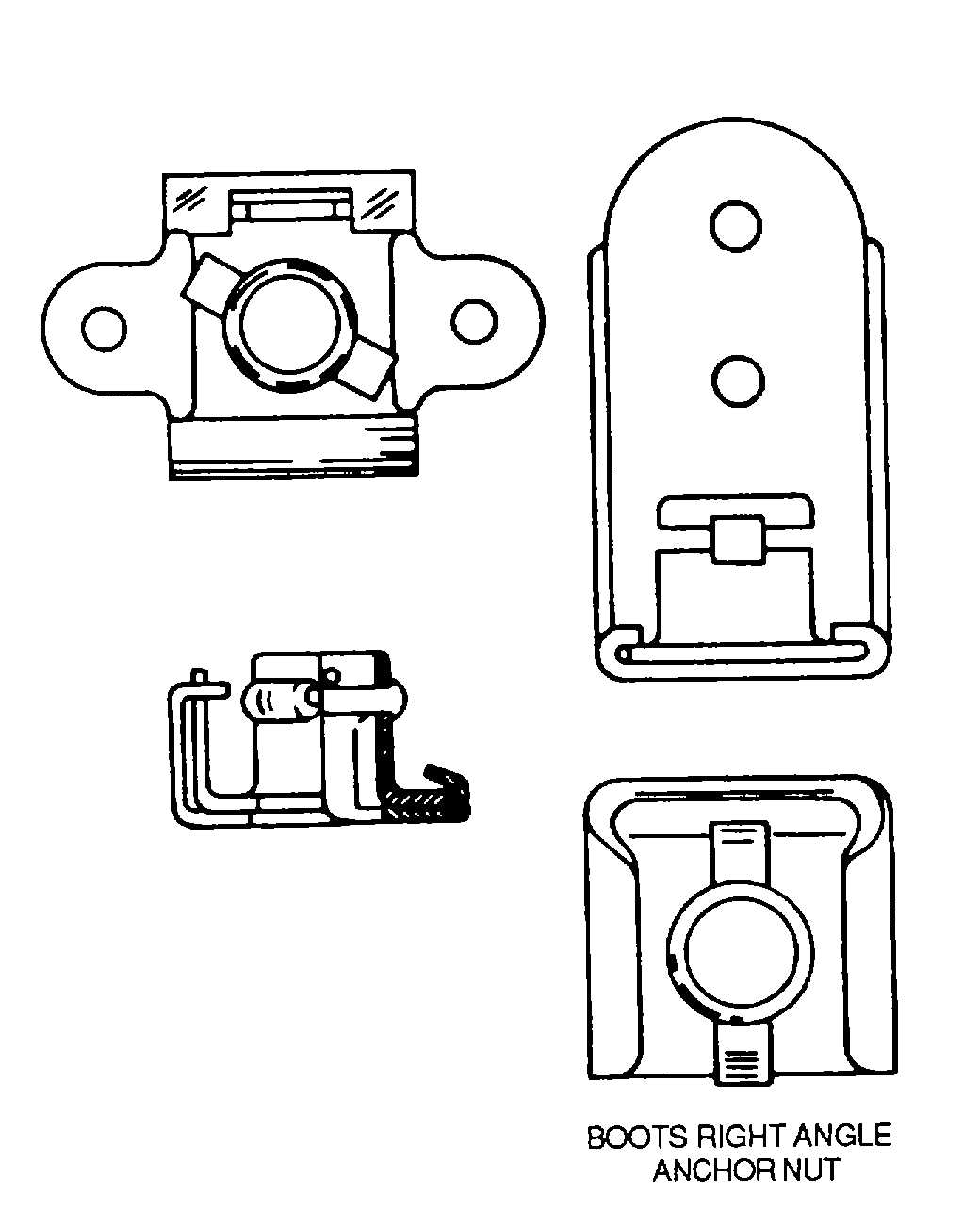
Figure 2-18. Plate Nut Styles
CAUTION
Self-locking nuts shall not be reused in applications where failure could
cause loss of the aircraft or danger to life.
(3) Installation. Self-locking nuts, like most aircraft parts, are precision-built. To perform their job effectively, they
must be handled properly.
(a)
Instructions. The procedures for installing self-locking nuts are as follows:
1 Since self-locking nuts are purposely made with a tight locking insert, a wrench must be used to tighten
them.
2 Start nut and bolt connections by hand to prevent cross threading.
3 Use drift pin carefully when lining up nut and screw holes to avoid damaging nut.
4 Prevent overstressing bolt and nut threads by using a torque wrench and recommended torque values
specified in table 2-9.
5 Use proper tools at all times. Socket and box end wrenches are preferred to open end wrenches as they
will not damage the corners of the nuts.
(b)
Limitations. Self-locking nut installation limits are shown in figure 2-21. The limit criteria as
applicable are as follows:
•
Round- or chamfered-end bolts or screws, as shown in figure 2-21, must extend at least the full round or
chamfered area plus one thread pitch through the nut.
•
Flat end bolts or screws, as shown in figure 2-21, shall extend at least two thread pitches through the nut.
•
Nuts, made to the minimum height, that are used with bolts of maximum length may give the indication
that too many threads are exposed and the grip of the bolt is pushing against the face of the nut. There is
no assurance that this is not true until the nut is removed and inspected for scratches.
2-29