TM 1-1500-204-23-6
f.
Safety
Cable
Identification
Stamp.
In
applications where the user requires a logo or ID code to
be a permanent part of the safety cable installation (for
warranty or tractability), it shall be applied by the safety
cable manufacturer to one or more surfaces of the
square end fitting of the safety cable. Only impression
stamping is permitted, no paint, ink or labels are
acceptable. See figure 2-91.
Figure 2-91. Safety Cable Identification Stamp.
g.
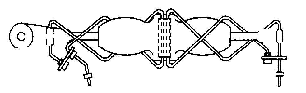
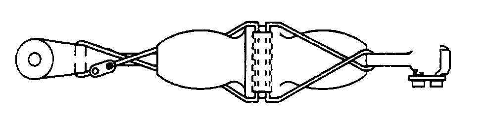
Safety Cable on Turnbuckles. The standard
procedure for securing turnbuckles with safety cable is
shown in figures 2-92 and 2-93.
(1)
A self looping safety cable is threaded
through the turnbuckle. One end shall be wrapped in
one direction around the turnbuckle. The safety cable is
then threaded through the hole in the self looping
jumper, and terminated with the appropriate application
tool.
(2)
Safety cable diameter selection for
turnbuckle applications, 0.032 inch diameter safety
cable shall be used on assemblies where cable diameter
is 1/16 inch or smaller, and 0.040 inch diameter safety
cable or greater shall be used on turnbuckle cable
diameters greater than 1/16 inch.
Figure 2-92. Routing of Safety Cable on
Turnbuckles
Figure 2-93. Example of Final Safety Cable
Turnbuckle Installation
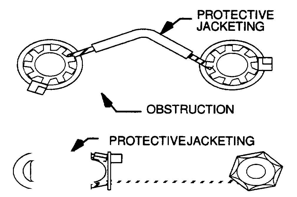
h.
Safety Cable Jacketing for Protection. (See
figure 2-94). It is recommended to use a tubular jacket
over safety cable when it is installed in a location where
it is in contact with (or may contact) surfaces which may
damage the safety cable. A tubular jacket material shall
be capable of meeting the temperature range of the
application, it shall be resistant to oil and chemicals.
Figure 2-94. Cable jacketing for Protection
2-20. Safety Cable Application Tools.
a.
Procedures. When safety cable is used, the
following basics apply for the application tools and
calibration equipment.
(1)
Minimize mixing of safety wire and
safety cable.
(2)
Install the ferrule cartridge into the tool
body under the handle grip.
NOTE
When loading and using the safety
cable hand tool, be certain that the
correct size safety cable kit is being
used with the tool.
(3)
Install the safety cable through the
fasteners to be secured.
(4)
The nose can index to four positions at
90°
increments. To select the position, push the nose in
towards the tool and rotate to the desired position.
Release the nose, if the nose does not lock into the
indexed position, turn it slightly until it does. See figure
2-95.
(5)
Insert the free end of the cable through
the ferrule in the cartridge, and remove the ferrule by
pulling the cable away from the end of the cartridge.
See figure 2-95.
Change 2 2-88