TM 1-1500-204-23-6
Table 2-19. Safety Cable Minimum Crimp
Requirements (Pull-Off Load)
Nominal Cable
Diameter
Inch (mm)
Safety Cable
Construction
Minimum
Pull-Off Load
Ibf (N)
0.020 (0.51)
1 x 7
30 (133.4)
0.032 (0.81)
3 x 7
70 (311.4)
0.040 (1.02)
7 x 7
110 (489.3)
(10) Hole Alignment. Undertorquing or
overtorquing to obtain proper alignment of the holes is
not permitted. Apply recommended torque values to
parts to be secured, and alignment of holes shall be
evaluated before attempting to proceed with safety
cable.
CAUTION
The maximum bend exit limit of
safety cable, when applied to a
threaded fastener head, shall be
1350. This does not apply to hose
fittings, electrical connector coupling
mechanisms,
turnbuckles,
and
similar applications where the safety
cable is constrained by the shape of
the component being secured.
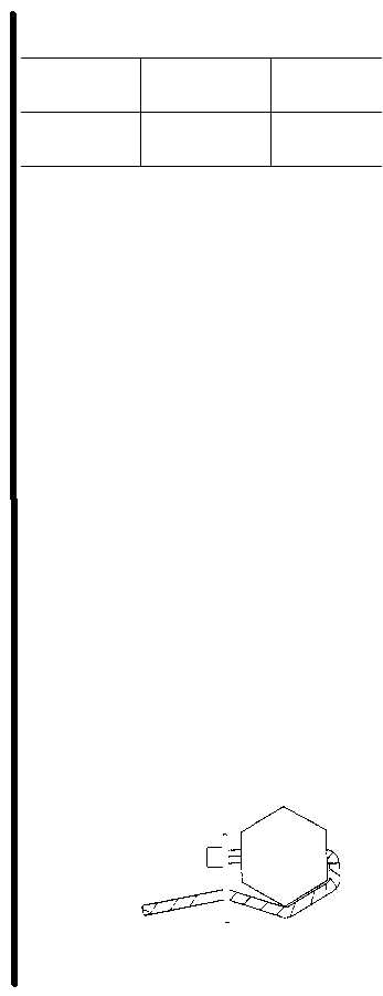
(11) In applications where safety cable shall
be required to exceed the 1350 maximum bend exit limit
in order to achieve neutral to positive pull on a threaded
fastener head, a self looping device which is secured to
the safety cable by the safety cable manufacturer may
be used to obtain a secured installation as shown (figure
2-86).
CAUTION
This method should only be used in
applications where the safety cable
can not "flip" over the corner or over
the head of the fastener being
secured.
Figure 2-86. Self Looping Safety Cable in High
Bend Exit Application
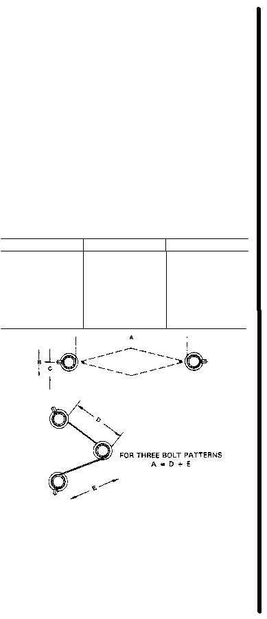
(12) Cable Flex Limits. After installing
safety cable, the maximum flex between termination
points shall be no greater than that specified in the
Cable Flex Limit Table (table 2-20).
NOTE
When calculating the flex limit (B & C)
of safety cable which is installed
through three fasteners, the A = D + E
formula shall apply (see figure 2-87).
The total length of safety cable from the
point where it exits the first fastener, to
the point where it enters the last
fastener shall be measured. The
corresponding length from table 2-20,
column A shall be used to determine the
flex limit.
Table 2-20. Flex Limits, Inch (mm)
A
B
C
0.5 (12.7)
0.125 (3.18)
0.062 (1.59)
1.0 (25.4)
0.250 (6.35)
0.125 (3.18)
2.0 (50.8)
0.375 (9.52)
0.188 (4.76)
3.0 (76.2)
0.375 (9.52)
0.188 (4.76)
4.0 (101.6)
0.500 (12.70)
0.250 (6.35)
5.0 (127.0)
0.500 (12.70)
0.250 (6.35)
6.0 (152.4)
0.625 (15.88)
0.312 (7.94)
Figure 2-87. Safety Cable Flex Limits
NOTE
Light
finger
pressure
of
approximately 2 pounds shall be
applied at mid-span when inspecting
total flex limit of installed safety
cable.
Change 2 2-86