
NAVAIR 01-1A-505-3
TO 1-1A-14-3
TM 1-1500-323-24-3
014 02
1 September 2011
Page 28
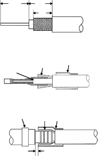
0.189"
0.177"
(4.8 mm)
(4.5 mm)
1. Strip cable to dimensions shown, IAW
0.138"
NAVAIR 01-1A-505-1 WP 009 00.
(3.5 mm)
2. Slide ferrule on the cable.
3. Slide inner conductor in the center contact
Shield
Ferrule
combed
until bottomed.
Center
4. Crimp center contact using tools in Table 3
Contact
Bottomed
and NAVAIR 01-1A-505-1, WP 013 00.
Outer Contact
7. Slide outer contact body over center
Shield
Ferrule
contact.
8. Fold shield over crimping area.
9. Slide ferrule over shield. Ensure the 0.020
inch clearance is maintained during crimping.
10. Crimp ferrule using tools in Table 3 and
NAVAIR 01-1A-505-1, WP 013 00.
11. Rotate contact in crimping tool 45 and
0.020"
make a second crimp on the ferrule.
0.5mm
12. Insert contact into connector insert using
tools in Table 3.
Figure 30. 617131, 617031, 617133 and 617033 Coaxial Contact Buildup