
NAVAIR 01-1A-505-3
TO 1-1A-14-3
TM 1-1500-323-24-3
014 02
1 September 2011
Page 31
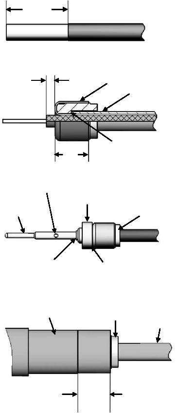
0.364"
(9.25 mm)
1. Strip outer cable jacket to dimensions
shown, IAW NAVAIR 01-1A-505-1 WP 009
00.
0.047"
Cable Shield
1.2 mm
Cable Jacket
2. Slide ferrule on the cable till butted against
cable jacket.
3. Comb out exposed shield braid.
4. Fold combed braid over ferrule.
5. Trim center dielectric to dimension shown.
Ferrule butted
against cable
0.177"
jacket
4.5 mm
Center conductor visible in center
contact inspection hole.
6. Slide the rear insulator on center dielectric
Rear Insulator
Center
till it butts against shield braid.
Contact
Ferrule
7. Slide inner conductor in the center contact
until bottomed against rear insulator. Ensure
center conductor is visible in the contact hole.
8. Crimp center contact using tools in Table 3
and NAVAIR 01-1A-505-1, WP 013 00.
Center contact butted
Rear insulator butted
against rear insulator
against shield braid.
Outer Contact
Ferrule
Cable
9. Slide outer contact body over center
contact sub-assembly till fully seated.
10. Crimp outer contact body in the
designated area using tools in Table 3 and
NAVAIR 01-1A-505-1, WP 013 00.
Designated
Crimp Area
Figure 34. 617103, 617003, 617104, 617004, 617105 and 617005 Coaxial Contact Buildup