
TM 1-1510-262-10
(11) dB Systems, Universal Audio Interface Model 270. The I/F Ampliier accepts and ampliies differ-
ential receiver/transceiver CMWS health and warning audio from the ECU. The I/F Ampliier routes this audio to
Junction Box Audio Receiver 2352A3 where it is distributed to the Pilot Intercom Audio Control 2352A1 and Co-Pi-
lot Intercom Audio Control 2352A2.
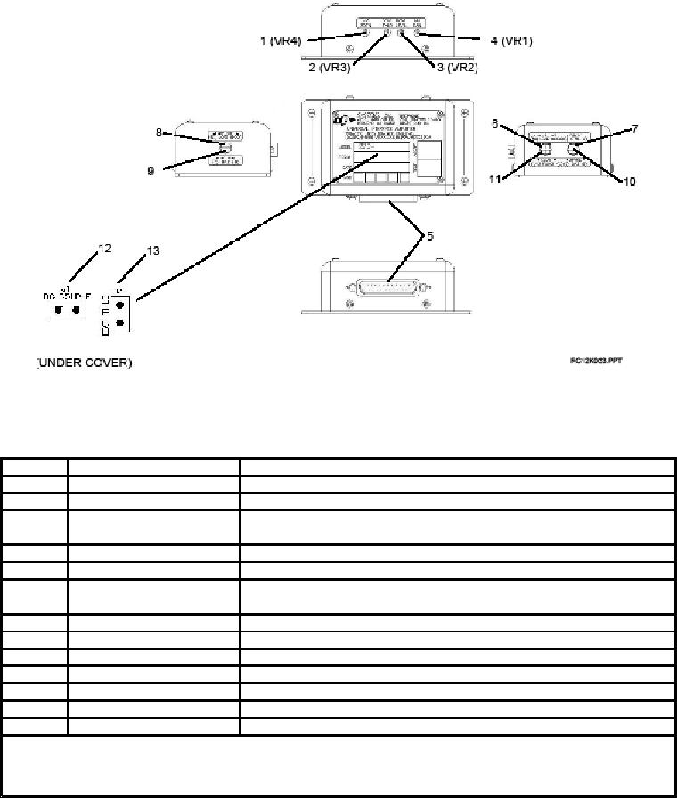
Figure 4-15. I/F Ampliier (Front, Back and Side views)
Table 4-10.
I/F Ampliier Switch Functions
ITEM #
Switch/Control/Indicator
Description
1
Not used, setting does not matter.
MIC SDTN (VR4)
2
Not used, setting does not matter.
VOX THLD (VR3)
3
Adjusts the audio level between the Audio input channel and the
RCVR LEVEL (VR2)H
Audio Output channel.
4
Not used, setting does not matter.
MIC GAIN (VR1)
5
25-pin "D" subminiature connector.
CONNECTOR (P1)
6
AUDIO OUT LOAD (MS5)
Set to 600. Allows selection of 8 OR 600 load compatibility
for the Audio Output channel.
7
Not used, setting does not matter.
RELAY CTRL (MS1)
8
Not used, setting does not matter.
MIC OUT LOAD (MS4)
9
Not used, setting does not matter.
MIC IN BIAS (MS3)
10
Not used, setting does not matter.
SPARE BIAS (MS2)
11
Not used, setting does not matter.
RELAY FUNCT (MS6)
12
Not used, setting does not matter.
DC COUPLE (J1)
13
Not used, setting does not matter.
EXT. THLD (J2)
NOTE
Access to mini-switches is through access holes in the sides of the cover. Access to jumpers J1
and J2 is by cover removal.
4-20