TM55-2840-251-23
5-3 ACCESSORY GEARBOX (AVIM) (Continued)
5-3-1 REMOVAL
CAUTION
Do not turn engine in a horizontal position.
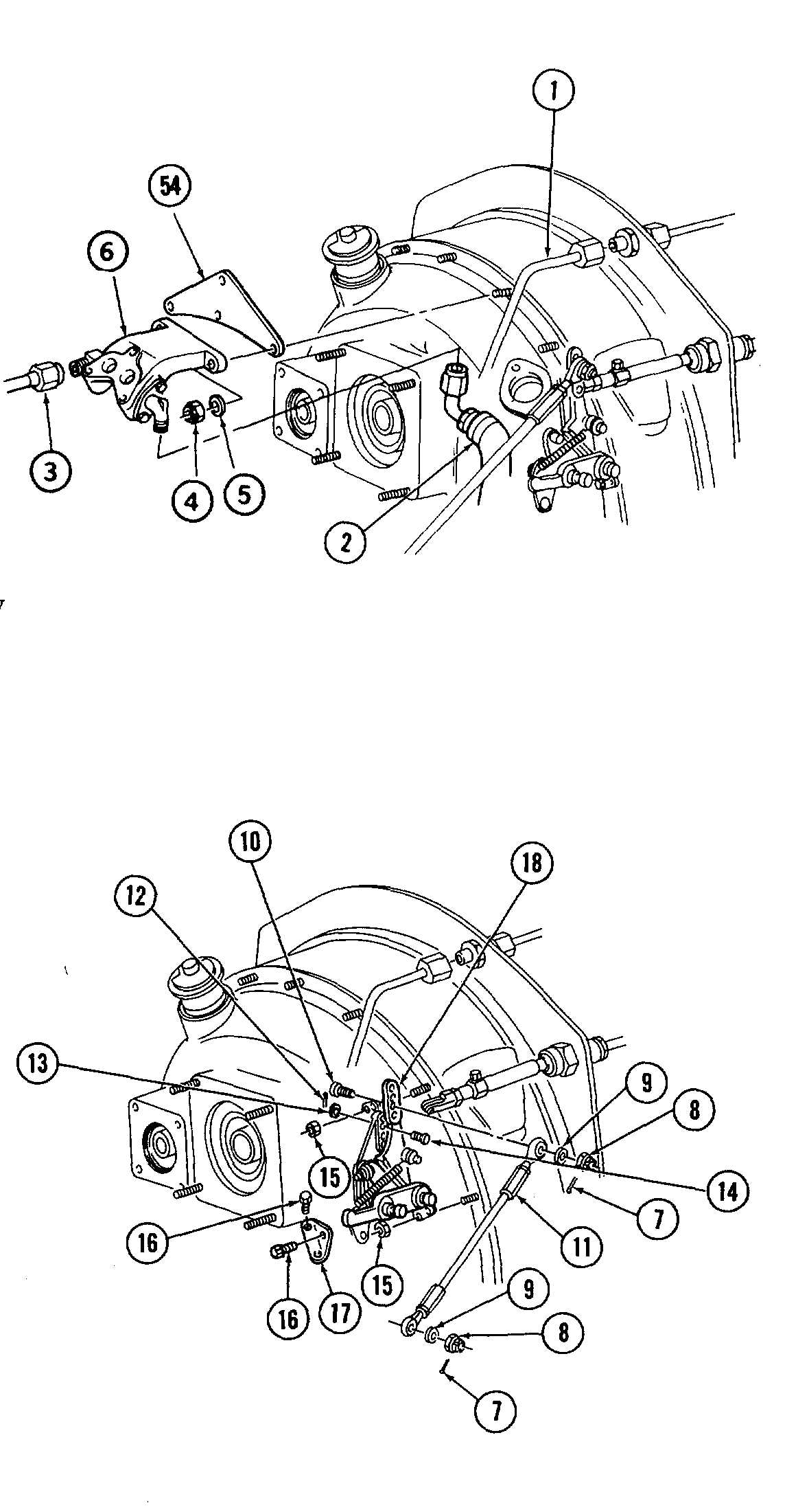
1. Remove lockwire and disconnect tube assemblies
(1), (2) and (3).
2. Remove nuts (4), using Wrench (T.55), washers (5)
and FWD brackets (6) and lifting brackets (54).
3. The accessory gearbox diaphragm is secured to the
accessory gearbox housing by four countersunk screws,
plain washers and self-locking nuts, which must nor be
removed at this stage. The four screws are located at
the following positions: 4th, 8th, 14th and 18th in
clockwise rotation, assuming 1st to be at the 12 o'clock
position.
4. Remove cotterpins (7), nuts (8), washers (9), bolt
(10) and disconnect control rod (11).
5. Remove cotterpin (12), washers (13) and pin (14).
6. Remove nuts (15), using Wrench (T.55), bolts (16),
plate (17) and lever assembly (18).
GO TO NEXT PAGE
5-11

