TM 1-1500-204-23-1
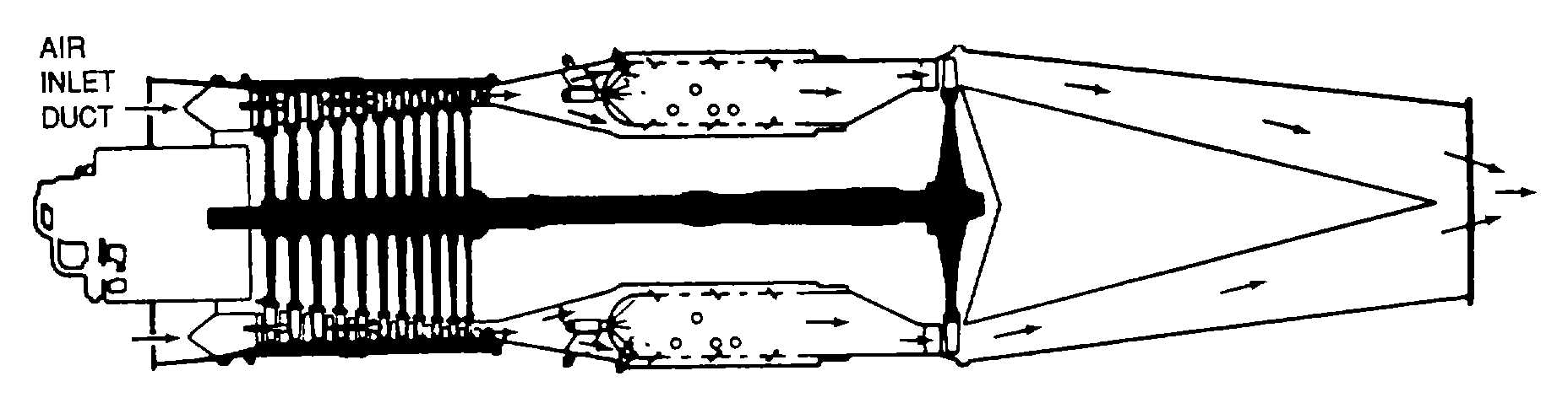
Figure 8-3. Single Entrance Inlet Duct (Axial-Flow Engine)
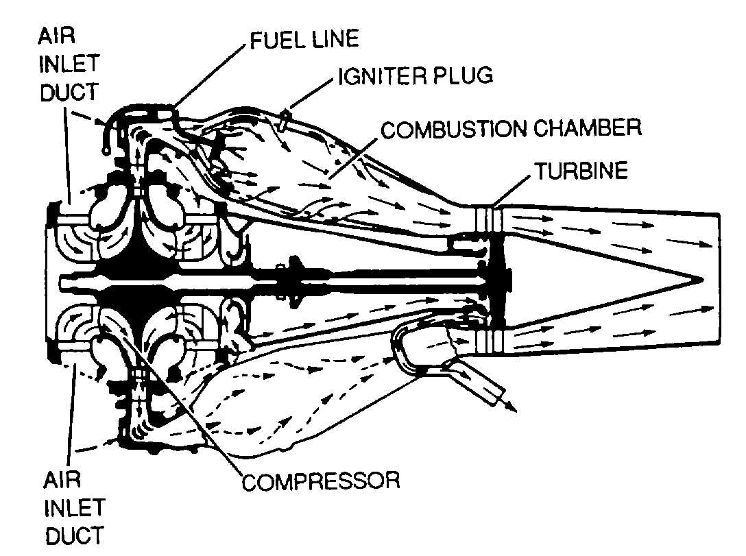
Figure 8-4. Divided Entrance Inlet Duct
(Centrifugal-Flow Engine)
b Particle Separators. Particle separators, as shown
in figure 8-5, prevent foreign particles from entering the
compressor section of turbine engines. Air enters the
engine through the swirl frame. Swirl vanes direct the
air into a rotating or swirling pattern. Sand, dust, and
other foreign objects are separated by centrifugal action.
These objects are carried to the outer section of the
main frame and into the scroll case. Particles are drawn
from the scroll case by the blower and are blown out the
aircraft discharge duct. The relatively clean air that
remains after particles are separated is carried to the
front frame deswirl vanes, which straighten the air flow
before it enters the compressor inlet.
c. Compressor Section. The compressor section of a
turbine engine has many functions. Its primary
functions is to supply air in sufficient quantity to satisfy
the requirements of the combustion burners. The
compressor must increase the pressure of the mass of
air received from the air inlet duct and then discharge it
to the burners in the quantity and at the pressure
required. A secondary function of the compressor is to
supply bleed-air for various purposes In the engine and
aircraft.
(1) Centrifugal-flow compressor. The centrifugal-
flow compressor consists basically of an Impeller (rotor),
a diffuser (stator), and a compressor manifold, as shown
In figure 8-6. The compressor achieves its purpose by
picking up the entering air and accelerating it outwardly
by centrifugal action.
(2) Axial-flow compressor. In the axial-flow engine,
the air is compressed while continuing in its original
direction of flow, thus avoiding the energy loss caused
by turns. From inlet to exit the air flows along an axial
path and is compressed at a ratio of approximately
1.25.1 per stage. The axial-flow compressor has two
main elements, a rotor and a stator, as shown in figure
8-7. The rotor has blades fixed on a spindle. These
blades Impel air rearward in the same manner as a
propeller because of their angle and airfoil contour. The
rotor, turning at high speed, takes In air at the
compressor inlet and impels it through a series of
stages. The action of the rotor increases the
compression of the air at each stage and accelerates it
rearward through several stages With this increased
velocity, energy is transferred from the compressor to
the air in the form of velocity energy. The stator blades
act as diffusers at each stage, partially converting high
velocity to pressure. Each consecutive pair of rotor and
stator blades constitutes a pressure stage. The number
of rows of blades (stages) is determined by the amount
of air and total pressure rise required. The greater the
number of stages, the higher the compression ration.
8-4