TM 1-1500-204-23-1
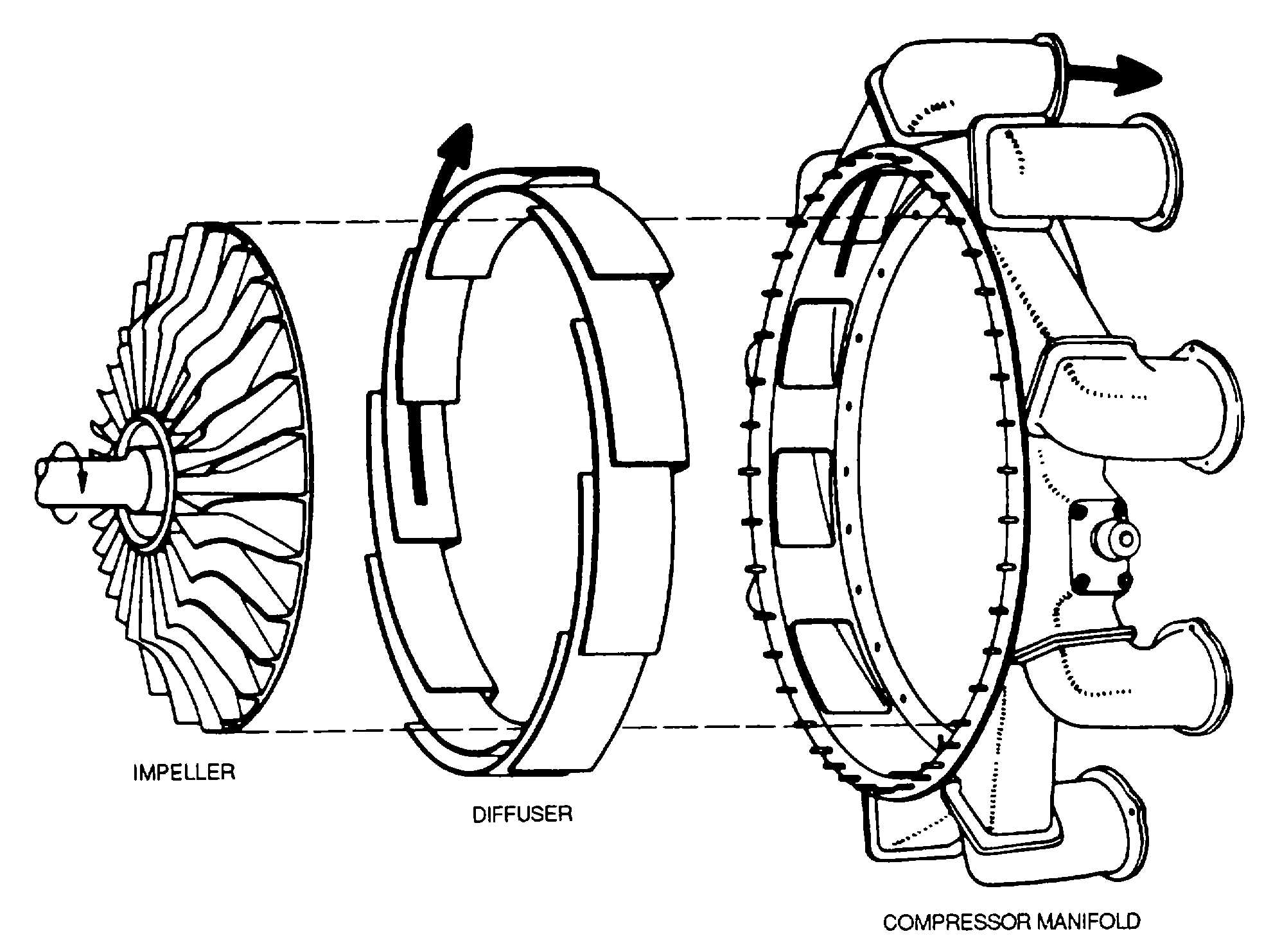
Figure 8-6. Centrifugal-Flow Compressor Components
g. Exhaust Section. The exhaust section of a turbine
engine is made up of several components, each of
which has its individual functions. Although the
components have individual purposes, they also have
one common function. they must direct the flow of hot
gases rearward in such a manner as to prevent
turbulence and at the same time Impart a high final or
exit velocity to the gases.
h. Accessory Section. The accessory section of a
turbine engine has various functions. The primary
function is to provide space of the mounting of
accessories necessary for operation and control of the
engine. Generally, it also includes accessories
concerned with the aircraft, such as electric generators
and fluid power-pumps Secondary functions include
acting as an oil reservoir and/or oil sump, and housing
the accessory drive gears and reduction gears.
i. Governors and Fuel Controls. Governors and fuel
controls used on turbine engines are explained in the
following paragraphs.
(1) Governors. The speed-sensitive control and
speed-set governor are discussed in the following
paragraphs.
(a) Speed-sensitive control. The speed-sensitive
control, as shown in figure 8-11, is mounted on the
tachometer pad of the accessories housing. It contains
three switches which are actuated at certain speeds by a
flyweight system. During a start, one switch turns on the
fuel and ignition, parallels fuel pump elements,
energizes the starting fuel enrichments system when
fuel enrichment switch is on, and closes the drip valve.
Another switch shuts off the ignition, deenergizes the
drip valve (which is then held closed by fuel pressure),
and shifts the fuel pumps from parallel to series
operation. Still another switch shifts the temperature
datum control from start limiting and limits the
temperature datum valve to a certain reduction of
engine fuel flow.
8-6