TM 1-1500-204-23-1
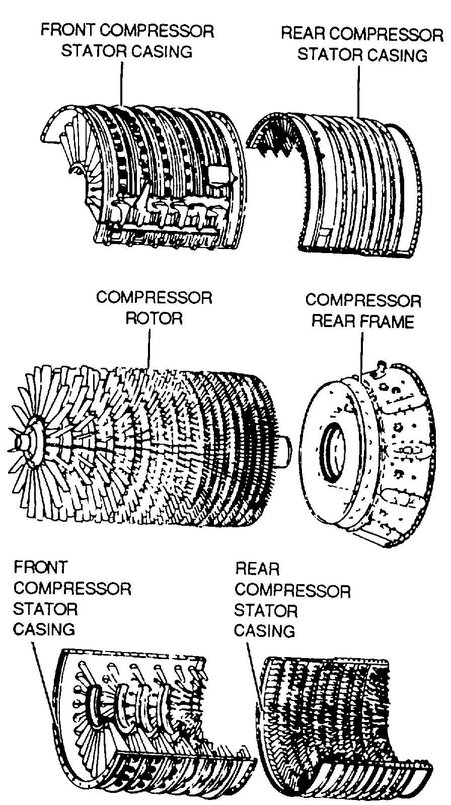
Figure 8-7. Rotor and Stator Components of an
Axial-Flow Compressor
(b) Speed-set governor. The speed-set governor,
as shown in figure 8-12, controls the position of the
governor servo. It is a centrifugal, permanent-droop
type governor driven by the engine high-speed rotor (N2)
through a gear train. As engine speed increases, the
fly-weights tend to move outward, lifting the speed set
pilot valve. Conversely, when engine speed decreases,
the fly-weights move inward and the pilot valve is
lowered. The power lever in the cockpit positions the
speed-setting cam in the fuel control unit to manipulate
a system of levers and thus control the compression of
the speeder spring. The speeder spring exerts force on
the speed-set pilot valve. The condition of on-speed
indicates the speeder spring force and the flyweight
force are equal.
(2) Fuel controls. Fuel controls can be divided into
two basic groups hydromechanical and electronic. The
fuel control senses power lever position, engine rpm,
either compressor inlet pressure or temperature, and
burner pressure of compressor discharge pressure.
These variables affect the amount of thrust that an
engine will produce for a given fuel flow.
(a)
Hydromechanical
fuel
controls.
Hydromechanical
fuel
controls
are
extremely
complicated and are composed of speed governors,
servo systems, sleeve and pilot valves, feedback or
follow up devices, and metering systems.
(b) Electron/c fuel controls Electronic fuel
controls contain the same Items as the hydromechanical
fuel control as well as amplifiers, thermocouples, relays,
electrical servo systems, switches, and solenoids.
Figure 8-8. Can-Type Combustion Chamber Arrangement
8-7