TM 1-1500-204-23-1
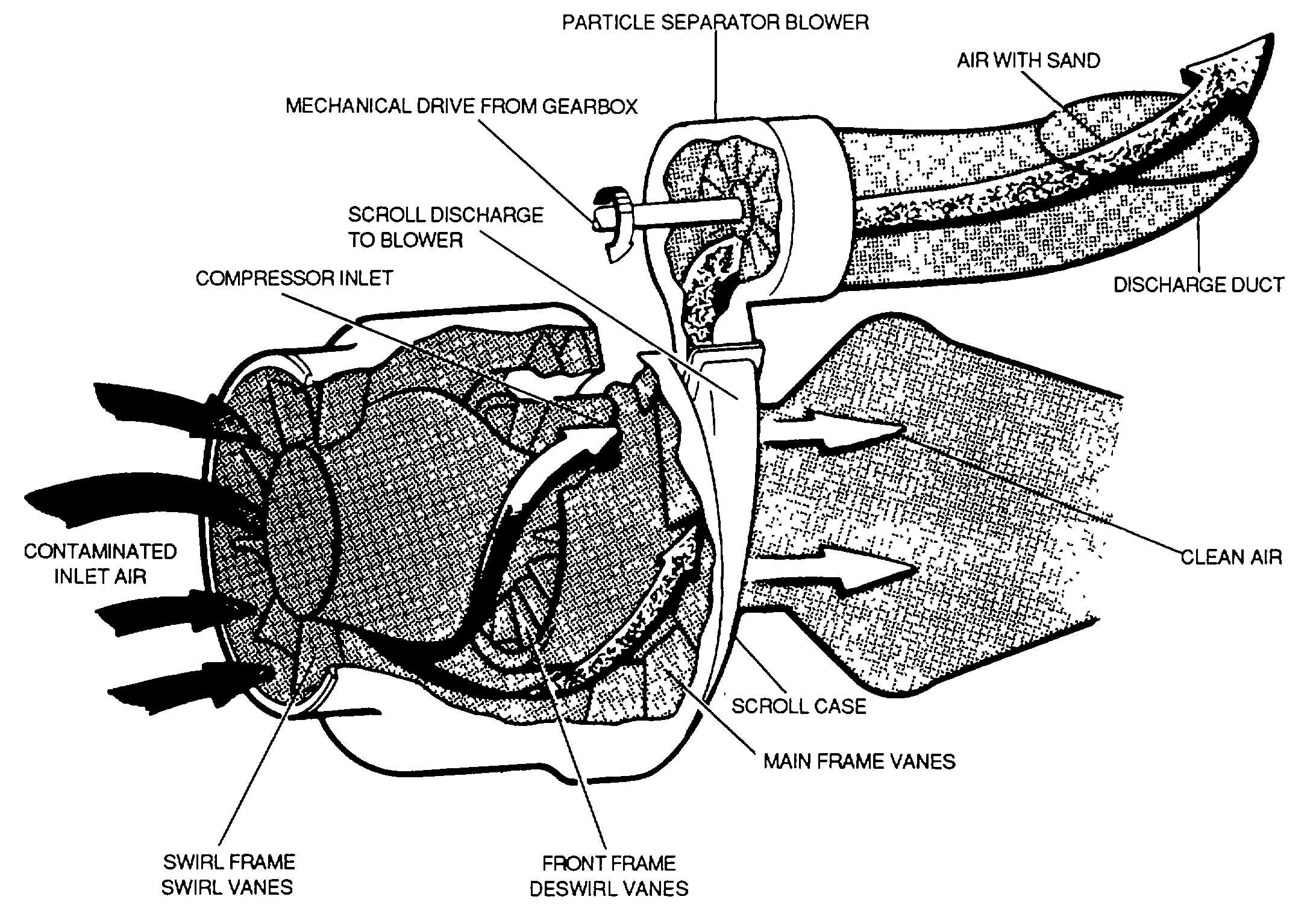
Figure 8-5. Particle Separator
d. Diffuser Section. The diffuser increases the
compressor discharge area and reduces the speed of
the centrifugal impeller airflow, causing the air pressure
to increase. This pressurized air is directed to the
combustor through the diffuser case The diffuser case
mounts on the rear flange of the compressor stator it
directs compressor discharge air to the combustion
chamber.
e. Combustion Section. The combustion section
houses the combustion process, which raises the
temperature of the air passing through the engine. This
process releases energy contained in the air-fuel
mixture. The major part of this energy is required at the
turbine to drive the compressor. The remaining energy
creates the reaction or propulsion and passes out the
rear of the engine in the form of a high-velocity jet. The
location of the combustion section is directly between
the compressor and the turbine sections. The
combustion chamber is always arrange coaxially with
the compressor and turbine regardless of type, since the
chambers must be In a through-flow position to function
efficiently.
Can-Type. The can-type combustion is typical of
the type used on both centrifugal and axial-flow engines
Figure 8-8 illustrates the arrangement for can-type
combustion.
The
engine
combustion
cans
are
numbered in a clockwise direction facing the rear of the
engine with the No. 1 can at the top. The can-type
combustion consist of an outer case or housing, which is
perforated stainless steel (highly heat resistant) (See
Figure 8-9).
f. Turbine Section. The turbine transforms a portion
of the kinetic (velocity) energy of the exhaust gases into
mechanical energy to drive the compressor and
accessories. This is the sole purpose of the turbine and
this function absorbs approximately 60 to 80 percent of
the total pressure energy from the exhaust gases. The
turbine assembly consists of two basic elements, the
stator and the rotor, as does the compressor unit.
These two elements are shown in figure 8-10.
8-5


