
NAVAIR 01-1A-505-3
TO 1-1A-14-3
TM 1-1500-323-24-3
010 02
1 September 2011
Page 14
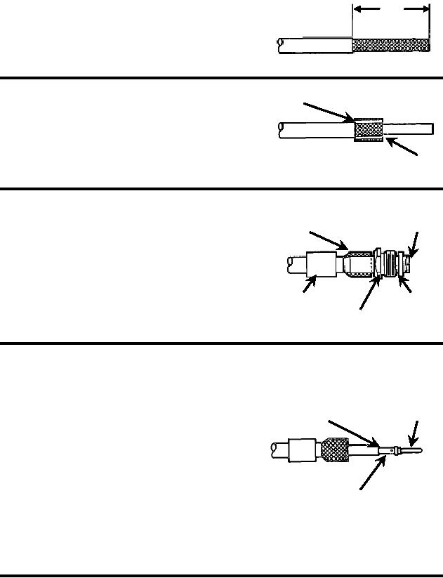
A. Cut Cable End Square, Leaving Enough Cable For
3/4"
Adequate Strain Relief Without Excess Slack. Using
Coaxial Cable Stripper, Strip Jacket 3/4 Inch From
End.
Crimp Sleeve
B. Slide Crimp Sleeve over Shield Until Flush With
Edge Of Jacket. Trim Shield Flush With Edge Of
Crimp Sleeve.
Trim
C. Flare Shield. Do Not Comb Out Individual Shield Flared Shield
Strip Flush
Strands. Slide Nut over Retainer. Slide Retainer
Assembly over Dielectric and Under Shield Until
Seated Against Shield and Jacket. Using Sharp Knife,
Strip Dielectric Flush With End of Retainer.
Crimp Sleeve
Retainer
Nut
D. Remove Retainer Assembly. Insert Center
Trim Center
Conductor Into Center Contact. Trim Center Conductor
Conductor As
Center
As Required To Seat Center Conductor Remains
Required To Seat
Contact
Visible In Contact Inspection Hole.
E. Crimp Center Contact Using M22520/2-01
Crimp Tool Frame and M22520/2-23 Positioner.
Ensure Center Conductor Remains Visible In Contact
Inspection Hole.
Contact Inspection Hole
Figure 8. MIL-DTL-26518 Size 8 Shielded Contact Assembly (Sheet 1 of 2)