
NAVAIR 01-1A-505-3
TO 1-1A-14-3
TM 1-1500-323-24-3
014 02
1 September 2011
Page 45
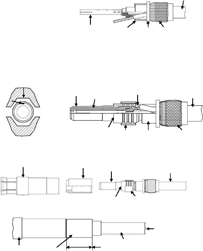
Cable
11. Slide the intermediate ferrule over the
insulating bushing till fully seated.
Center
Shield
Ferrule
Insulator
Contact
Braid
Bushing
12. Slide the center contact insulator over center contact assembly.
13. Slide the intermediate contact over the sub-assembly.
14. Put the second conductor in the barrel slot of the intermediate contact.
15. Slide the ferrule over the second contact, ensure ferrule does not extend past the intermediate
contact shoulder.
16. Crimp ferrule to intermediate contact using tools in Table 5 and NAVAIR 01-1A-505-1, WP 013 00.
Ensure second conductor is aligned with one of the hexagonal flats before crimping.
Crimp Die
Flat
Intermediate Center
Second
Contact
Conductor
Contact
Cable
Insulator
Second
Conductor
Contact
Insulator
Shield
Ferrule
Shoulder
Bushing
Braid
16. Slide intermediate contact insulator over intermediate contact.
17. Slide outer contact over intermediate contact insulator till all components are seated.
Intermediate
Outer
Contact
Contact
Insulator
Intermediate
Cable
Contact
Contact
Ferrule
Shoulder
18. Crimp the outer contact in the area indicated below using tools in Table 5 and NAVAIR 01-1A-505-1,
WP 013 00. Continue to maintain inward pressure on cable while crimping to ensure all parts a properly
seated
Push in on Cable
while crimping.
Cable
0.186"
Outer
Outer Contact
4.72 mm
Contact
Crimp Area
Body
Figure 40. 617150, 617050, 617151 and 617051 Triaxial Contact Buildup (Sheet 2 of 3)