
NAVAIR 01-1A-505-3
TO 1-1A-14-3
TM 1-1500-323-24-3
014 02
1 September 2011
Page 39
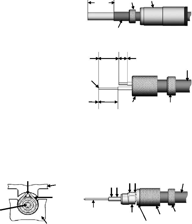
Alignment
1. Slide alignment boot on cable prior to
Boot
Ferrule
0.472"
stripping.
12 mm
2. Slide ferrule over cable jacket prior to
stripping.
3. Strip outer cable jacket to dimensions
shown, IAW NAVAIR 01-1A-505-1 WP 009
00.
Cable Jacket
0.282"
0.118"
7.1 mm
3 mm
4. Fold shield braid over the cable jacket.
Cable Jacket
5. Trim center and intermediate conductors to
Center
correct length.
Conductor
6. Strip center and intermediate conductors to
dimensions shown, IAW NAVAIR 01-1A-505-
1 WP 009 00
0.268"
6.8 mm
Ferrule
Combed
Shield
7. Put the two wires in the insulator until it hits the shield braid.
8. Slide wire one into center contact and wire two into intermediate contact.
9. Crimp center contact and intermediate ferrule using tools in Table 5 and NAVAIR 01-1A-
505-1, WP 013 00. Ensure wire two side of intermediate ferrule is against crimp tool anvil.
Second Conductor
Intermediate
(Ensure second conductor
Contact
Center
is facing anvil)
Crimp
Contact
Cable
Area
Crimp
Jacket
Anvil
Area
Intermediate
Ferrule
Center
Center
Contact
Contact
Intermediate
Shield
Ferrule
Ferrule
Braid
Insulator
Die Enclosure
Bushing
Figure 38. 617165, 167065, 167165021 and 617065021 Triaxial Contact Buildup (Sheet 1 of 2)